Simulating Multi-Stage Cold Forging to Reduce Time-to-Market and Production Costs
Cold forging process design presents a process layout problem. Due to the variety of working procedures and the complexity of the workpiece, it is very difficult to design a cold forging process without the designer’s knowledge and experience.
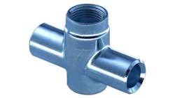
The case study presented here involves finite-element analysis of a multi-stage cold forging process for a heat pipe fitting made by Zoppelletto S.p.A., an Italian company operating in the cold forged components market for more than 50 years. Cold forging is the company’s core business and in the past 30 years Zoppelletto has evolved from a craft manufacturer into an advanced industrial enterprise, able to produce millions of specialty components and guaranteeing timely production for delivery.
Production focuses on five principal sectors: thermo hydraulic, oil-pressure hydraulic, automotive, office furniture, and hardware for bolts, hinges, etc. Zoppelletto’s technical department has at its disposal the latest CAD-CAM capabilities for manufacturing production equipment and forging tools, engineered and produced in-house. For mass production of small or medium-sized components, multi-station automatic cold forging presses are used. In cold forging, initial materials are formed progressively to final shapes by automatic and synchronized operations, including shearing, upsetting, forward and/or backward extrusion and piercing. The development of forging simulation software presented the challenge of how best to introduce its use into forging companies. Its effective introduction has required advances in the user-friendliness of the simulation software and its application to a wide range of problems.
Planning a Production Process
Because the choice of a process plan affects the design, manufacture, and maintenance of the dies, cold forging research emphasizes improvement of process planning. The design of a multi-stage forging process sequence involves determining the number of preforms along with their shapes and dimensions. The best designs for preforming operations can be identified by their ability to achieve adequate material distribution; this is one of the most important aspects in the cold forging processes.
Traditionally, forging-sequence design is carried out using mainly empirical guidelines, experience, and trial-and-error, which results in a long process development time, and high production costs. Using computer-aided simulation techniques in metal forming before physical tests may reduce the cost and time of the process design.
Many computer-aided approaches based on approximate analysis and empirically established design rules have been published.
These techniques do not always provide detailed information concerning the mechanics of the process. However, the finite-element method has been shown to provide more accurate and detailed information, and thus has been widely adopted for simulating and analyzing various metalforming processes.
Finite-element analysis (FEA) has become one of the most widely used engineering tools and has been adopted in practically all fields of industry due to advances in both software capabilities and the availability of more powerful computers.
In addition, since FEA can simultaneously predict all the necessary stress-strain states in both die and workpiece, extensive applications of this method have been reported for large-scale deformation forging processes. Many researchers have focused on the effective strain, damage and flow patterns within the workpiece during cold forging processes. However, up to now, work on the process planning of cold forging has concentrated on rotationally symmetric parts. Work on non-axisymmetric parts has not been so actively pursued, due to difficulties of shape cognition and expression, calculations of the process variables such as forming load, effective strain, effective stress, and so on.
In this study, numerical simulations were carried out for the design of a cold-forged heat pipe fitting used in thermo-hydraulic applications. The simulation was performed using the Transvalor ColdForm software. A forging experiment of the heat pipe fitting also was carried out using the designed tool set. From a comparison of the results between the simulation and the experiment, it was found that the simulation showed good agreement with the experimental result.
Process Description and Modeling
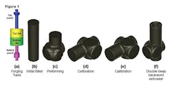
Figure 1 shows the sequence of the analyzed multi-stage, non-axisymmetric cold forging process. The cold forging process-sequence to form the heat pipe fitting consists of four operations: preforming, first and second calibration, and double deep backward extrusion.
A 6,300-kN, multi-station general-purpose mechanical knuckle press and automatic workpiece transfer between stations is used. The cooling time for the workpiece was 2.86 sec., which for each stage was calculated from the end of one forging operation to the beginning of the next one. The top dies in each forming stage and the bottom dies in the first and third operation are floating, and driven by the contact forces exerted during the forging process. Bottom punches are fixed during the forging process and act as workpiece extractors.
The material used for the workpiece is a low-carbon alloy steel, whose chemical composition is listed in Table 1. Tools are assumed to be rigid with an infinite elasticity modulus and a constant temperature of 20°C. The heat-transfer coefficient is taken as 20 kW/m2. The die-workpiece interface is characterized by the constant factor friction law usually used for bulk metal-forming problems, t=mk. Here, t is the frictional shear stress, m is the friction factor, and k is the shear flow stress. The shear friction coefficient (m) was set to 0.4.
Process Sequence Optimization
The main objective of the process sequence design in this study is to obtain intermediate preforms that will produce a near-net-shape product. Also, design constraints, such as the limit of the press capacity and the avoidance of surface defects, should be satisfied.
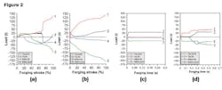
As can be seen in the load-forming time relationship (Fig. 2a), the top punch load is almost constant at the beginning of the operation. However, immediately after the top die touches the bottom die, the punch load suddenly increases and reaches its maximum value at the end of the process.
The maximum load in this process is 133 metric tons, which is less than the limit of the available press capacity of 642 metric tons. In the fourth operation, shown in Fig. 2d, a large deformation also occurs in the workpiece near to the walls of the punches and dies.
From the load-forming time relationship (Fig. 2d), it is noted that the load applied to the dies increases steadily as the top punch moves forward. As expected, approaching the end of the operation this load becomes almost constant. In this stage, the maximum punch load is estimated to be 50 metric tons, which can be identified as the minimum value of the current four-stage process. On the other hand, the maximum load on the top punch and the bottom die during the second calibration is 142 and 155 metric tons, respectively (Fig. 2b.) During the third stage (the second calibration operation) the top punch doesn’t contact the workpiece, and therefore the maximum load revealed is zero. Moreover, due to the lower forging loads reached by the other tools in this third forging stage, the elimination of this operation is suggested. This gives a shorter development lead-time, lower cost production, savings in tool material costs, and the development of a higher precision part.
Defects Evaluation
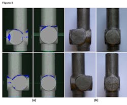
During the preforming operation, the billet deforms asymmetrically and underfilling occurs. Underfilling problems are limited by the use of multiple forming stages. Figure 3 shows the reduction of the underfilling areas (in blue) at the die corners obtained by the FE analysis, which is consistent with the experimental observation.
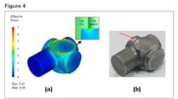
By using FEM simulation, it was found that defects occur in each stage of the forming sequence. The numerical results coming from each forging stage are validated by means of experimental observations. In particular, during the second-stage operation (calibration), a great amount of material flows to fill the area between the top punch and die, due to an excessive top punch stroke (Fig. 4.)
Benefits of FE method
In the “forming” process chain, the simulation of the forming process offers substantial opportunities for improvement: for example optimizing the component and tools may provide opportunities to enhance process reliability. The numerical simulation carried out by using Transvalor Forge software could be extended in various directions in order to accommodate such new requirements.
In metal forming, as mentioned above, process simulation is used to predict metal flow, strain, temperature distribution, stresses, tool forces, and potential sources of defects and failures. In some cases, it is even possible to predict product microstructure and properties as well as elastic recovery and residual stresses.
The main reasons for simulation are reducing time-to-market, reducing tool development costs, predicting the influence of process parameters, reducing production cost, increasing product quality, improving the understanding of material behavior, and reducing material waste. These things are achieved by accurately predicting the material flow, determining the filling of the die, accurately assessing net shape, predicting if folds or other defects exist, determining the stresses, temperatures, and residual stresses in the workpiece, and determining the optimal shape of the preform.
Also, as simulation allows us to capture behavior that cannot be readily measured, it provides deeper insights into the manufacturing process.
Steps in Integrated Product and Process Design
There are several principal steps involved in integrated product and process design for metal forming. The geometry (shape, size, surface finishes, and tolerances) and the material are selected for a part depending on the functional requirements. The design activity represents only a small proportion (5 to 15 percent) of the total production costs of a part. However, decisions made at the design stage determine the overall manufacturing, maintenance and support costs associated with the specific product.
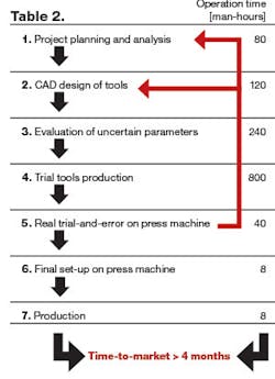
Once the part is designed for a specific process, the steps outlined in Table 2, lead to a rational process design.
Applying the FE method in this complex cold forging process of a heat pipe fitting involves:
• The conversion of the assembly-ready part geometry into a formable geometry.
• The preliminary design of tools/dies necessary to perform the operations used for forming the parts.
• The analysis and optimization of each forming operation and associated tool design, to reduce process development time and trial-and-error.
• Manufacturing of tools and dies by CNC milling, or by EDM or another similar technology.
Ascertaining process-specific factors in production engineering by means of process simulation promotes efficient manufacturing of products of specified properties. Three objectives are emphasized:
• Review of the feasibility of an existing concept for manufacturing of a product.
• Assessment of product characteristic.
• Enhanced understanding as to what really occurs in a process, for the purpose of optimizing the manufacturing technique.
To achieve these goals, however, it only makes sense to use process simulation if this is more economical in the long run than experimental repetition of the actual process.
Focusing on a new product development chain of a company’s multi-stage cold-forged component (Table 2), the actual time-to-market revealed is more than four months. Moreover, due to the company’s costly trial-and-error method, this time-to-market can increase exponentially (see red lines arrows on Table 2.)
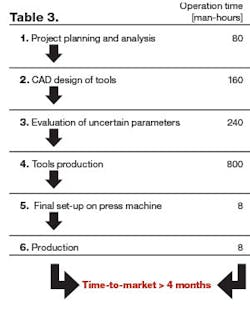
Using the FE method, the company’s estimated time-to-market expected is less than four months (Table 3.) In this case the traditional time-consuming and costly trial-and-error method has been replaced with a simulation-based approach using Transvalor Forge, which now can address the whole manufacturing process.
The two approaches may seem similar if we look at the use of CAD/CAE design of tools instead of real trial-and-error on the press machine, but it’s important to highlight that normally this trial-and-error step is the most time- and cost-consuming part of the traditional method of designing a new component. The number of “red” iterations needed to arrive at a good process can be very high if unexpected problems occur, and this can have a great impact on the total time-to-market. As more simulation skill is developed in the organization, the difference between the traditional approach and the FEM approach increases. This looks not only at man-hours, but also more deeply at other aspects of the cost of a new component.
Completely removing the trial-and-error iterations saves the costs of trial tool production, so the time to recover the entire software and training investment decreases dramatically to some months (less than one year), depending on how widely this approach is adopted.
Moreover, it is important to notice that one hours’ loss of production, due to a traditional time-consuming trial-and-error step, costs about €180.00-230.00 (est. $230.00-$290.00.) For this reason, Zoppelletto S.p.A. has decided to break with the traditional method of new product development and has committed to using Transvalor Forge software to support its development process.
Conclusions
Using finite-element methods as tools results in cost reduction, time savings, and improvements in product quality for Zoppelletto S.p.A.. The design of the deformation sequence and forging tools can be modeled before, and also during, production. This allows the engineer to identify process deficiencies easily, leading to cost and time savings.
Such modeling efforts can be very valuable in identifying inhomogeneous deformations, such as folds that could not easily be detected through regular visual inspection. Moreover, based on industrial experience, this approach is estimated to reduce the time required to set up new forging cycles by about 40%.
Fabio Bassan is a professor in the Department of Management and Engineering, University of Padua, Vicenza, Italy. Contact him at [email protected]
The author expresses his gratitude to Zoppelletto S.p.A., in particular to Eng. Luca Zoppelletto, for providing information about the multi-stage cold forging process used to support this analysis. Thanks are extended as well to Eng. Marcello Gabrielli, EnginSoft S.p.A., for his interest in the work and helpful discussions, advice, and suggestions.
