For the past seven years, QForm3D has enabled forging producers to perform 3D simulations simply by selecting “solid body models” as the initial geometry data for the dies and the workpieces. For simulating hot, warm, and cold forming processes, the software predicts material flow defects, identifies the temperature distribution, and calculates the load and consumption of energy for the deformation.
The program behaves like a “virtual forging shop where the user has control of all the variables,” according to the developers. A user can develop the sequence of technological operations required to produce the forging, including upsetting, blocking, and finishing blows, as well as selecting the required equipment and lubricant required. Preliminary and intermediate operations, like reducer rolling, heating, cooling, and flash trimming, can be included as well in the technological chain.
Predict forging defects with precision is one of QForm3D’s strongest featurs, they explain. A completely automated code generates an adaptive mesh for the most complicated shapes of the deformed billet surface, including when it collapses and a lap emerges. The program detects areas where laps are likely to occur and locally increases the mesh density in those areas. As a result the laps are indicated with the highest precision.
Surface-to-surface contact is also treated automatically and the lap surface is clearly shown by a cloud of red spots, indicating defect location and depth. The program traces the defects through the sequence of blows and shows the location of the defects in the finished product.
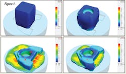
In Figure 1, an arm forging has several laps due to improper die design. The user can see where and when the defects are initiated, and how they propagate inside the forged part body.
In addition to laps, there are other defects that may appear during forging of complex parts. QForm3D has special under-surface flow lines to detect defects that may appear below the surface. If an undersurface defect occurs, clearly visible loops are pulled into the forging that identify these flow-through defects.
Figure 2 simulates a hammer forging of the hook, with no laps and a die that is completely filled. However, a more thorough view of how the die is filled (Figure 3) reveals some conditions that may cause a defect. Undersurface flow lines give clear evidence of the defect formation.
As Figure 4 shows, some of the lines deviate from the surface, making loops. Figure 5 is a more detailed view of the defect formation, with the lines displayed layer-by-layer.
To fix this defect, the preform shape has to be modified. To check the effectiveness of the change, the simulation must be run again. For more effective analysis, a simulation project may include several variations — each one a complete technological sequence of several consecutive operations. This allows the user to analyze several variants of the technology side-by-side, in order to select the best one.
