Optical flame detectors sense radiant energy from an open flame by employing infrared, visible, and/or ultraviolet sensors, usually in signal-processing combination within a single detection instrument. The design and installation of optical flame detection systems is to provide early and fast detection of an ignition event and subsequently execute automatic mitigating actions and alarm notification to people and systems potentially affected by the fire alarm.
To achieve a high-performing flame detection system, application engineers start with a detailed hazard evaluation of the area to be protected and select the optimal flame detection sensing technology to match the radiant energy emission signature expected from the flammable materials to be detected. Since different fuels emit unique flame spectra, not all detectors can detect flames equally. Further, the presence of optical contaminants and non-fire radiant energy sources within monitored zones can have a significant impact on the performance of certain sensing technologies and installation locations. In some cases, additional optics protection accessories are required to ensure 24/7 availability.
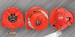
Customers have a variety of fixed optical flame detection technologies to choose from. The most common types are Multi-Spectrum Infrared (MSIR) and Ultraviolet/Infrared (UV/IR) flame detectors (Fig. 1). MSIR detectors use multiple infrared sensors monitoring different spectral frequencies for hydrocarbon fire detection. MSIR detectors offer an extended field of view optimal for large area monitoring and are a good option where maintenance is limited. However, they can be blinded by wate, ice, & snow. Careful aiming in outdoor applications is recommended. UV/IR detectors use a single UV & IR sensor and perform ‘AND gate’ voting to detect most hydrocarbon fires and some non-hydrocarbon fires. They provide fast alarm response and an optional UV-only pre-alarm is useful in electrostatic paint and transformer applications. UV/IR detectors have a comparatively shorter detection range and can be blinded by silicones, dirt, soot, oil, solvents, water and ice.
It is recommended to always confirm fuel/flame detectability before specifying an optical flame detector and look for certified performance test reports to confirm your proposed flame detection performance specification. This specification will serve as the fundamental coverage template enabling proper assessment of different onsite installation points and alignment angles.
Onsite Coverage Considerations
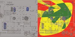
After the hazardous area analysis is completed, onsite coverage using the optimal flame detection technology and preliminary performance specification can be assessed. Common approaches include geographic or scenario coverage assessments. The geographic approach assesses coverage within a defined geographic fire ignition zone covered by one or more detectors, while the scenario approach specifies the most likely fire scenarios within a zone that can be detected with consideration given to frequency and catastrophic magnitude using defined coverage arrangements. In both cases, known physical obstructions must be identified and layouts must ensure proper coverage despite these obstructions (Fig. 2).
In some applications, cross-zone voting will be used to enhance reliability. An example is one flame detector in alarm will drive audible/visual alarm devices, and two detectors in alarm (2oo2) within a single zone, or even 2oo3 voting will drive mitigation or ESD action. Anytime cross-zone voting is desired, redundant or triplicated coverage of the high-risk zones will be required, and a coverage map is highly recommended for all cross-zone voted coverage applications.
Installation Best Practices
Installation contractors should be qualified, licensed, and understand what it is they are installing. Detailed documentation and training should also be readily available on your specific system installation requirements. Here is a short list of typical installation concerns and best practices:
1. System power supply should be properly sized and of proper type/rating. If a back-up power source is required, this should be monitored and properly sized. The power distribution design should include sub-breakers to enable powering up/down the system in logical sections rather than just all at once.
2. Ground fault monitoring is a common requirement. The best practice is to proceed on the premise that ground-fault monitoring is required.
3. All detector power and signal cabling requirements should be clarified including cable shields and terminations as required. Conduit seals, breathers, drains, and flexible conduit within 1 meter of the flame detector to enable proper flame detector aiming/alignment are generally required.
4. Detector mounting location structure must be solid and robust. Mounting structure vibration and movement is wholly undesirable and can lead to nuisance alarm problems. Also, all detection instruments should have a field tag attached with an instrument tag number easily visible.
5. A flame (and gas) detector setup table spreadsheet is recommended identifying instrument Tag #s for all detectors, installation location/elevation using GPS coordinates, programmable settings including sensitivity, time delay setting, latching or non-latching relay configuration, normally energized or normally de-energized relay coils, calibration information (gas detectors), and other configuration settings.
Commissioning Best Practices
After installation is complete and the system and all field devices are powered up and operating in a 100% fault-free mode, system commissioning can commence. It is important to note that system commissioning and integrated testing are two different concepts, and both must be completed successfully to properly evaluate flame detection system operation as well as its interaction with other systems.
Commissioning is a systematic process that provides documented confirmation that all system functions according to the intended design criteria set forth in project documents and satisfy the owner’s operational needs, including compliance with applicable laws, regulations, codes, and standards. A commissioning checklist is generally developed that spells out specific system functions, critical input and output signals, devices, and operational logic that must be tested and validated before the system can be considered fully commissioned.
The system commissioning checklist should generally include line item checks for proper functional testing of power redundancy/battery back-up (if required), system ground-fault monitoring (if required), critical output functions and related input actuation, field testing methodology for all flame detectors --and manual fire alarm signaling devices including alarm voting criteria (cross-zone or multi-sensor confirmation).
The best test of any optical flame detection system is a real onsite fire test using the fuel type and fire size called out within the project’s optical flame detection performance specification. While optimum with respect to evaluating flame detection system performance, in many cases this type of real fire performance testing is either unacceptable or not practical due to fire risk or operational issues. In this case, the owner/end-user will need to identify the desired methodology of confirming onsite flame detector coverage and response time delivered by the system during the commissioning phase.
After completion, the Commissioning Engineer typically prepares and submits a commissioning report including as-built drawings, cause/effect logic, and updated system database of all information developed, changed or modified during the full commissioning process.
Operations, Maintenance, and Training
A fire detection system maintenance logbook should be managed and maintained that includes all system activities and events logged by instrument tag number. Typical logbook entries include Alarms, Faults, Tests, Visual Inspections, and Cleaning activities logged by tag number, date & time, and person. In addition, a routine visual inspection procedure should be established where the frequency of inspection points is defined including detector faceplate status LED’s are visually inspected for normal or trouble status, visual confirmation that no foreign material or obstructions are present that will block the field of view of any detector, and that alignment angles appear normal. If there are any optics protection accessories installed, these should also be inspected to ensure they are working properly. Finally, a functional test using a test lamp should be routinely executed. Be sure to bypass any suppression discharge apparatus before performing a functional fire detector alarm test.
Operations and Maintenance personnel should generally know how to perform basic system diagnostic and troubleshooting procedures, including how to:
- Identify where and when a fire alarm or fault occurred
- Bypass the alarm function on a system for routine detector service
- Perform a visual inspection and clean the optics of a flame detector
- Locate the system logbook and electrical schematics
- Troubleshoot a basic trouble/fault condition
- Communicate with a flame detector using HART
- Perform a response test using a test lamp
- Aim/re-aim a flame detector using information from the detector setup table
- Set the rocker switches on a flame detector
- Follow recordkeeping procedures for logging troubles, alarms, cleaning activities, etc.
- Power-up/power-down a system
Understand annual system inspection and alarm response testing plan and who to call for technical assistance Significant technical advancements have occurred over the past decade which has improved the baseline performance of optical flame detectors. However, it remains incumbent upon the end-user or their assigned contractors to execute due diligence in performing proper analysis and evaluation of the onsite fire hazards and ensuring proper detection technology selection and coverage along with proper installation, operations, and maintenance practices to attain a continuously reliable, high-performing optical flame detection system.


