Gaining a Better Understanding of Die Design and Wear
No die forging producer is unaware of the value of tooling, the need to handle dies carefully and use them effectively, and to maintain their design accuracy and process reliability. Why forging dies are so valuable is no mystery, but knowing the secrets of die design may be the best way to understand how to maintain that value.
In recent years, simulation technology and high-speed computer analysis have made die design more precise and reliable and made it possible also to examine the variables in die design. All this progress makes it possible too for forgers to understand better the mysteries of die design.
Here are two examples of the research making forging die design more accessible.
Design and Analysis of a Hot Forging Die
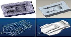
In their research, P. Naresh, A.V. Hari Babu, V. Madhava, and M.Sudhakar Reddy conducted a wear analysis of a closed die at the final stage of a hot forging process. The preform geometry of the part to be forged was measured by a Coordinate Measuring Machine (CMM), in contrast to the CAD model of the die and the worn die provided by a forging operation.
The hot forging operation was carried out at a workpiece temperature of 2,012°F (1,100°C) and die temperature of 572°F300°C for a batch of 678 on a 1,600-ton mechanical press. The die and workpiece materials were AISI L6 tool steel and DIN 1.4021, respectively.
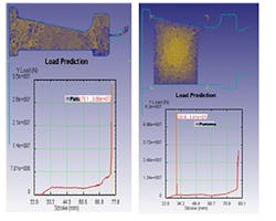
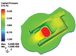
The simulation of forging process for the die and the workpiece were carried out by the finite volume method using MSC. Super Forge. The flow of the material in the die, die filling, contact pressure distribution, sliding velocities and temperature distribution of the die were investigated. In a single stroke, the depth of wear was evaluated using Archard’s wear equation with a constant wear coefficient; the depth of wear on the die surface was evaluated using finite volume simulation results, and then the total depth of wear was determined.
To compare the wear analysis results with the experimental worn die, the surface measurement of the worn die was done on CMM. By comparing numerical results of die wear analysis with the worn die measurement, the dimensional wear coefficient was evaluated for different points of the die surface, and a value of dimensional wear coefficient was indicated.
From the finite volume analysis of a closed-die hot forging and wear measurement of the worn die, the researchers concluded that, due to the sliding velocity between 0.2 and 0.5 m/sec and the contact pressure between 100 and 300 MPa on the contact interface of the die and the workpiece, mechanical wear is the predominant wear model.
In wear analysis of dies at the regions where high effective stresses may occur, the plastic deformation of dies must be taken into account.
On the regions close to the parting line, due to high effective stresses, plastic deformation appears. In the bottom part of the cavity, where the effective stresses are relatively lower, plastic deformation does not appear in these regions.
Operation temperature, contact pressure, sliding velocity and contact time have great effects on the depth of wear.
From the simulation of the hot forging process and comparison with the measurement of the worn die, the dimensional wear coefficient can be used as a good approximation for hot forging processes, under the same conditions.
Read and download “Design and Analysis of a Hot Forging Dies”.
Wear Analysis of Hot Forging Dies
Researchers C.E. Megharaj, P.M. Nagaraj, and K, Jeelan Pasha proposed to demonstrate how to use hammer capacity effectively by modifying the die design, such that the forging hammer can manufacture more than one connecting rod in a given forging cycle time.
To modify the die design, they sought to understand the parameters that are required for forging die design. By considering these parameters, they designed a forging die using the SolidEdge design modeling tool. This new design now can produce two connecting rods in the same capacity hammer.
Verification of the new design was set by verifying the complete filing of metal in die cavities without any defects in it, using DEFORM 3D analysis.
Before starting validation, it was necessary to convert 3D-generated models into .STL file format, to import the models into DEFORM 3D. After importing, the designs were analyzed for material flow into the cavities, and the energy required to produce two connecting rods in a new forging die design was measured.
In their example, the forging die design was found without any defects and the energy graph showed that the forging energy required to produce two connecting rods is within the limit of that hammer capacity.
Implementation of this project increased the production of connecting rods by 200% in less than the previous cycle time, they reported.
In their research Siamak Abachi, Metin Akkök, and Mustafa Ílhan Gökler analyzed the wear on a closed, hot die at the final stage of a component forging. The simulation of the forging process was carried out by commercially available software based on the finite volume method, and the depth of wear was evaluated with a constant wear coefficient.
By comparing the numerical results with the measurement taken from the worn die, the wear coefficient was evaluated for different points of the die surface, and a value of wear coefficient was proposed.
Among their conclusions, the researchers indicated that wear analysis of dies revealed that in the regions where high effective stresses may occur, the plastic deformation of dies must be taken into account, too.
Also, in the regions near the parting line, die plastic deformation appears due to high effective stresses that develop. In the bottom part of the cavity where the effective stresses are relatively lower, plastic deformation does not appear.
The operating temperature, contact pressure, sliding velocity, and contact time have great effects on the depth of wear.
Due to the sliding velocity between 0.2 and 0.5 meters per second and the contact pressure between 100 and 300 MPa on the contact interface of the die and the workpiece, mechanical wear is the predominant wear model.
(insert wear hot dies link)


