Jack It Up! How Screw Jack Technology Benefits Modern Industry
Introduction
Screw Jacks in industrial applications continue to provide proven results when used in appropriate designs and given proper maintenance. They reliably lift, position, support, and hold industrial loads. Once jack designs and application needs are understood, it is a simple matter to incorporate them into industrial systems for packaging, maintenance lifts, material handling, space technology, etc.
Machine Screw Jack Designs
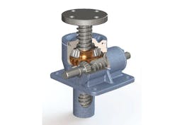
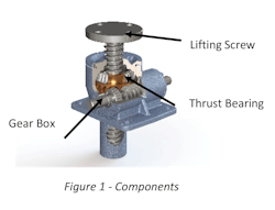
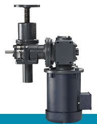
Basic components of machine screw jacks include lifting screw, gearbox, and thrust-bearing load support.
Using these components, jacks are built into three functional designs:
- Translating
- Keyed for Non-Rotation
- Keyed for Traveling Nut (KFTN)
Understanding each of the designs is foundational to selecting the best jack for specific applications. Once the jack design is selected, calculations for specific gearing properties and load capacity can be made.
Translating Jacks
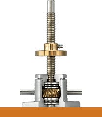
Translating design jacks are the most common and ideal for single and multiple jack systems. With this design, a driven worm acts on an internal gear, which drives the lifting screw to extend and retract. As the lifting screw translates through the body of the jack, inherent screw rotation is prevented by an attached load or mounting structure, which is anchored to resist rotation.
To prevent screw rotation, designers typically attach loads using one of the following techniques:
- The load is attached to a fixed plate or welded to the top of the lifting screw. Multiple jacks attached to a single load plate restrain screw rotation.
- The load is threaded onto machined vee threads at the screw end.
- External guides are used to support the load and prevent unwanted rotation.
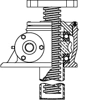
Keyed for Non-Rotation Jacks
Some loads do not prevent lifting screw rotation. These applications require a keyed for non-rotation jack. For machine screw jacks, a key, fixed to the jack housing and inserted into a keyway milled into the length of the lifting screw, forces the screw to translate without rotating. Since the screw cannot be rotated relative to the jack housing, designers must be careful to match mounting hole patterns or clevis orientation with the load to which it will be attached.
Less commonly used than translating design jacks, keyed jacks of this design are only available for machine screw jacks. Keyed ball screw jacks are rarely used, and a different design is employed to restrict the rotation of the lifting screw.
Designers should consider using keyed jacks for the following types of applications:
- Single jack applications where the load can rotate.
- Single or multiple jack applications that require the lifting screw to extend to meet the load. For instance, extending the lifting screw upward to engage a load.
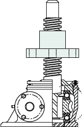
Keyed for Traveling Nut Jacks (KFTN)
KFTN jacks (sometimes referred to as rotating screw jacks) feature a lifting screw keyed to the gear as a single unit, forcing the screw to rotate instead of translating. A flanged traveling nut, attached to the load, is driven by the rotation of the lifting screw. This type of jack is ideal for applications that require a flush mount.
Designers need to consider these items when specifying KFTN jacks:
- The design must accommodate the overall length of the lifting screw from the base of the jack to the end of the screw.
- These jacks mount flush to the mounting surface.
- The turned end of the rotating screw is typically mounted into a bearing support to prevent “whipping” at the end of the screw.
Lifting Screws
Lifting screws can be either machine screws (usually ACME or Trapezoidal) or ball screws.
Machine screws are best for slow, infrequent motion and their efficiencies are typically 30% to 40%. This may seem low, but it is inefficiency that makes most machine screw jacks self-locking, eliminating the need for brake motors and other external locking devices. Lifting capacity coupled with inherent inefficiency and lower cost is the machine screw jack’s greatest strengths, making them a simple, robust, and cost-effective solution for lifting.
Ball screws, which are typically 90% efficient, allow the jacks into which they are built to be operated faster and more frequently using less power than their machine screw counterparts. They have the added benefit of a calculated B10 life for their ball bearings. This indicator arrives through statistical calculation. Ninety percent of ball nuts will meet or exceed the calculated life at a given load. Ball screw jacks are not self-locking and brake motors are required.
Internal Gear Sets
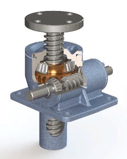
Two types of internal gear sets are available for machine screw jacks: worm gears and bevel gears.
Worm gears are most commonly used, and design capacities can range from a few hundred pounds to a few hundred tons. Each size worm gear screw jack is typically available in several gear ratios, to allow for travel speed and drive torque optimization for each application.
When selecting motors to power these jacks, one must keep in mind that efficiency ratings are given for a specific input rpm. Operating worm gear screw jacks at slow speeds may require more torque.
Spiral bevel gears are available in static capacities up to 100 tons. They offer increased gearbox efficiency in rotating the internal nut or jackscrew. Bevel gear jacks that are coupled with machine screws generally retain their self-locking features because of the inefficiency of the machine screw.
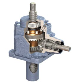
When bevel gear sets are coupled with ball screws, efficiencies are increased allowing them to be capable of near-continuous duty cycles. In addition, unlike worm gears, spiral bevel gears have a predictable life.
Operating the Jack
Manually adjusting a jack generally requires 3 to 100 turns at the input shaft for each inch of linear travel. This varies from jack to jack depending on the gear ratio and screw lead. As loads increase, the input torque needed to move them increases proportionally. Manually raising some loads may require additional gear reduction, requiring even more turns per inch of travel. With manual operation, designers need to consider the magnitude of the tangential force required at the diameter of the handwheel.
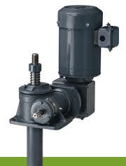
Most jacks are powered by AC induction motors, which offer the high starting torque desirable for screw jack operation. Although the main power selection guideline is a jack’s running torque. In addition to AC motors, screw jack systems are frequently powered by servo motors, hydraulic motors, and pneumatic motors. Follow manufacturer guidelines to size these motors.
The prime mover, or motor, is a critical choice for a jack system. It must accommodate the additional drag that each coupling, miter box, and pillow block adds to the system. This increased drag may be enough to boost horsepower requirements by 30% or more. Depending on each component’s location, system drag could require the use of larger shafts and gearboxes than originally determined.
Most structures are not rigid and uneven load distribution may exist. It is important to understand this during the installation of a system because the relative positions of unloaded jacks may not correspond to the actual load on each jack.
A simple test for load distribution is to check the running temperature of each jack with the load moving. For example, in a four-jack system, two jacks in opposing corners may run at 150⁰ F while jacks in opposing corners are only at 80⁰F. It is safe to assume that the two running at higher temperatures are supporting the bulk of the load and the other two are simply providing balance. To change this situation, simply loosen and rotate some of the couplings to adjust the relative position of the cooler jacks so they bear a more equal portion of the system load.
The effect of guides is another factor to consider in system design. Frequently, guides are used to prevent transmission of a side load to the screw jack. Properly designed guide systems will not add any significant load. However, poorly designed guide systems could increase drag, driving up the power requirements of the system.
Mounting Options for Jacks
Mounting choices for jacks depend on a jack screw’s configuration and how it is attached to the load and the stationary frame.
Available space will limit configuration choices. With a translating or keyed for non-rotation design, the screw jack may mount underneath the load and the base usually mounts to a stationary frame. In a platform lift, such an arrangement allows open access to the top. However, a recess must exist below the jack body to accept the retracted screw.
In a keyed-for-travel-nut (KFTN) design, the base of the jack mounts flush to a solid surface and the free end is usually supported in a flange bearing. Designers need to allow space for the fixed-length, rotating, lifting screw.
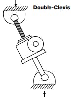
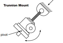
Special mounting options for double clevis or trunnion mounts are available when jacks must operate through an arc. These options are most suitable for single jack systems with shorter travel lengths.
Additional design considerations are required for multiple jack systems that move through an arc or when a long rise is needed.
Typical System Layouts
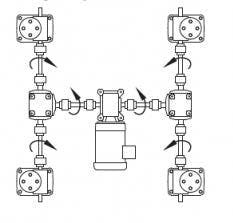
Single jacks are often strong enough to raise a given load. However, supporting a large load usually requires a different approach. Most screw jack systems consist of multiple jacks connected through a series of shafts and miter boxes, which helps simplify synchronization of the jack movement. Figure 12 illustrates a typical worm gear screw jack system, notice that miter boxes are required to complete this system.
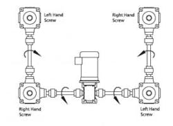
Multi-jack systems that use bevel gear jacks require fewer components. Jacks can be placed at the corners of the system, eliminating the need for miter boxes. When selecting multiple bevel gear jacks for an interconnected system, designers must pay attention to the output shaft rotation to ensure the jacks raise and lower in unison. To accomplish this jacks with left-hand screw threads are alternated with jacks having right-hand screw threads. Refer to figure 13.
Additional Considerations
Designers must consider the effect of column buckling when screw jacks are loaded with lifting screws in compression. Evaluating column buckling requires that the diameter of the screw, length of travel, magnitude of load, and method of support are considered. Larger capacity jacks may sometimes be selected for applications because they have larger diameter lifting screws and can support loads with longer stroke lengths without buckling.
Other factors such as travel speed and duty cycle sometimes come into play when sizing jacks for larger loads and faster cycle times.
Summary
This guide is intended to help engineers and designers quickly step through the process of selecting proper jack design, lifting screw type, and gear set option. Putting these fundamental principles into practice will improve the effectiveness of finished designs.
Executive Summary
Screw Jacks continue to offer robust solutions in the modern industry. Built with only three primary components, they offer design simplicity and are endlessly adaptable for lifting and positioning everything from conveyors and ergonomic lifts, to solar panels and earth station antennae.
The key to achieving proven results using screw jacks in the modern industry is understanding the fundamentals. We invite you to revisit the simple and reliable screw jack design principles that continue to deliver exceptional results.
Using the basic components of a gearbox, thrust bearing, and lifting screw, jacks are built into three designs.
Learn when to select translating, keyed for non-rotation, or keyed for traveling nut (KFTN) jacks. When to choose a machine screw or a ball screw and which gear set is best: worm gear or bevel gear.
Understand how jacks operate in systems and proper ways to mount them. Learn what smart designers look for and avoid when sizing screw jacks. Find out about JAX software, the designer’s tool for quick and accurate jack specifications.