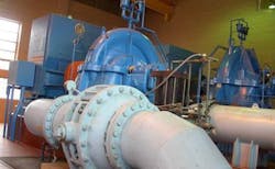
Water Flow Monitoring Helps Avoid Costly Fines
Many water distribution companies use a similar process: Collect water from a well with the help of water pumps, utilize a pond or reservoir to temporarily store the water and maintain a loading center to fill water trucks for transport. The problem is how to pump the maximum allowable volume of water on a day-to-day basis without exceeding the limits as dictated by local rules and regulations. Exceeding these limits can lead to costly fines—cutting profits in an already tightly competitive market. A distribution company contacted CAS in order to source a water flow monitoring solution.
Regulations in this case required that the distribution company not exceed 400,000 gallons of water in one day. In addition, the storage pond had a water level capacity of 18 feet; however, regulations stipulated that the water level could not exceed a maximum of 16 feet at any time. After review from the CAS Solution’s Team, it was determined flow sensors be installed to record the amount of water pumped from the well and a water level sensor was installed to record the height within the storage pond at all times.
Installation
CAS provided this company with a Water Flow Monitoring Solution capable of monitoring multiple sensor inputs. The data logger would track the incoming data on a 24 hour cycle. If the 400,000 gallon output level was reached, the data logger would signal to automatically shut down the water pump to prevent exceeding the 400,000 gallon limit. At the beginning of the next 24 hour cycle, the system would automatically reset to begin pumping again. If water levels in the pond exceeded the 16 foot level limit, the data logger would shut down the water pump and would only begin the pumping process again when the pond water level declined.
A dataTaker DT82E data logger was used to monitor the front end of the operation. The DT82E would record the data from two flow sensors and a submersible pressure transducer. The first flow sensor monitored the input of the water being pumped from the well while the second flow sensor monitored the output to the storage. The submersed pressure transducer monitored the water level of the storage pond.
Usage
While the trucks were collecting water from the storage pond, a DT80 model logger was monitoring and recording readings from the five flow sensors. The flow sensors were strategically located to fully monitor the actual volume of water being pumped. A wireless router was set up for both data loggers to collect the data for analysis, exporting, and recording. The data was easily retrieved from the dataTakers via the USB memory stick port. Data files are automatically separated by the serial number of the data logger which ensures that the data can be properly organized for reporting and archiving.
This data logging solution bundled a DT82E & DT80 data logger, seven (7) flow sensors and one (1) water level sensor. The setup allowed the water distribution system to be a self-monitored, stand-alone system. The data loggers were programmed to handle the sensors and manage the operation of the water pumps.
About the Author
CAS Dataloggers
Computer Aided Solutions, LLC. dba CAS DataLoggers is a distributor of data loggers, paperless recorders and data acquisition equipment.
We have the industry’s most complete selection of data logging equipment, with hundreds of different models from more than 18 manufacturers. With data loggers from 1 to 300 channels we can record temperature, humidity, force/strain, pressure, flow, voltage, current, resistance, vibration and other digital signals, in connection with serial (RS-232/RS-485), CAN/OBD or SDI-12 devices. We sell directly to end users and also work through a network of distributors and resellers throughout the United States, Canada, Central and South America.
We have been in business for over 20 years, and actively involved in selling data loggers and real-time systems since 2001. Our staff has over 100 years of total experience with different types of data acquisition and test and measurement equipment.
CAS can also provide value added services including on-site installation, wiring and packaging, engineering and design services and turn-key systems. We also provide configuration assistance, custom programming, custom system design and assembly, post-sales technical support, and repair and calibration services. Our development capabilities include custom data acquisition and data logging systems, test and measurement systems, and portable data collection systems.
