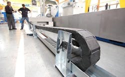
Guidelok Horizontal Carrier Provides Total Chip Protection
Metal chips can cause abrasion and wear in long-travel, gliding cable carrier applications. To combat this, igus has developed a horizontal guiding system called Guidelok, which is designed to keep the upper and lower cable carrier runs apart. The solution is ideal for applications in the machine tool industry up to 164 ft. (50m) and where chips can become trapped between a cable carrier’s upper and lower runs as they glide on top of one another.
Guidelok’s design keeps the upper and lower runs separate via spring-loaded roller support, which is pushed back as the cable carrier passes through, before snapping out again after the radius has passed. The upper run rests on the roller support and is not allowed to glide on the lower run.
The system not only works to reduce abrasion and wear caused by trapped chips and debris but also offers a number of other advantages. The system means the cable carrier can support itself over a longer distance. This enables users to choose a smaller version for the given length, saving overall costs and reducing the required push-/pull driving force. Guidelok keeps the upper and lower runs of the cable carrier separate from one another, which helps to minimize friction and wear and thereby increases service life.
A more traditional solution would have allowed large metal chips to settle in the inner radius between the upper and lower runs of the cable carrier, which could have caused damage. In contrast, the new system is ideal for such applications. Guidelok is also lower cost than most steel chains or sophisticated gliding systems
- Dirt can't get stuck between the sliding surfaces of the upper and lower run
- Modular system with few parts (also possible without lateral trough)
- Increase in unsupported lengths of energy chains
- Intelligent upper run guidance with pivoting roller supports
Applications:
- Machine tools
- Dirty environments
- Anywhere where gliding application is not recommended
(2 to 23.6 in.)
(6, 6.9, 7.9, 9.8, 11.8 in.)
(7.9, 9.8, 11.8 in.)
(3 to 18.2 in.)
(6, 6.9, 7.9, 9.8, 11.8 in.)
(5.9 to 18.2 in.)
(6.9, 7.9, 9.8, 11.8 in.)
(7.9 to 19.7 in.)
(9.8, 11.8 in.)
(7.9 to 23.6 in.)
(13.8, 15.7, 17.7, 19.7 in.)
(7.9 to 18.2 in.)
(7.9 to 19.7 in.)
