3 Monitoring Solutions for Li-ion Battery Packs
![GettyImages-538641146-[Converted].jpg](https://img.newequipment.com/files/base/ebm/newequipment/image/2019/06/newequipment_10339_gettyimages_538641146_converted.png?auto=format,compress&fit=fill&fill=blur&q=45?w=250&width=250)
The need for safe and portable power is increasing and so is the need for better monitoring and protection systems. Applications such as power tools require high-power battery systems in order to operate. These battery systems typically require cell combinations of five to seven cells in series to achieve higher power requirements. As the cell configuration increases, different approaches for monitoring and protection must be taken into consideration. This article compares 3 different architectures that use different monitoring and protection devices. The functionalities of components within each architecture, the required interfaces, and the advantages and disadvantages of each architecture are highlighted.
Monitoring and protections needed in a Li-ion battery pack
Accurate monitoring of cell parameters such as voltage, current, and temperature along with fuel gauging and cell balancing is the key to providing protection for a Li-ion battery pack. Because all of these parameters are analog signals, there is a need for an Analog Front End (AFE) whose main function is to measure and digitize the values for these parameters. These parameters are used as input to the digital logic to provide the required protection for packs, which could be accomplished through the same AFE chip or a different chip which contains the protection logic. These protections include over voltage, under voltage, over temperature, under temperature, short circuit and often several others. It is advisable to have primary and secondary protection, driven by 2 separate sets of components so that if primary protection fails, the pack is still protected by the secondary set.
Solutions under consideration
Three solutions that vary in their complexity, customizability and time required in the development cycle are considered here.
Solution 1: Fully integrated solution using a Battery Pack Manager (BPM) chip
This solution uses a BPM chip that has integrated AFE, fuel gauge and control logic to provide multiple levels of protection. A sample block diagram for this solution is shown in Figure 1. The example is one from Texas Instrument (TI) - BQ40z80. The chip monitors individual cell parameters and provides protection using high side N-channel MOSFETs. It also performs cell balancing and provides SMBUS communication to the outside world. The advantage with this solution is the simplicity, less development time and minimum set of components, but it lacks customizability.
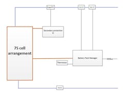
Figure 1
Solution 2: Using separate AFE and gas gauge
This solution is realized by combining an AFE with a compatible gas gauge. The AFE interfaces with the cells and monitors key parameters. Figure 2 shows the block diagram for this solution (as well as the 3rd solution to be discussed later).
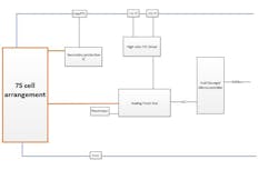
Figure 2
The AFE that is considered here is the BQ76930. It supports up to a 10-series cell configuration and has two low side MOSFET drivers. These drivers can be interfaced to a high side MOSFET driver if desired. The AFE alone cannot perform all the required management and protection tasks and depends on a separate chip to work along. In this example, it is a compatible fuel gauge which is the BQ78350. The fuel gauge interfaces with the AFE over I2C communication. It runs the logic for primary protection and commands the AFE to open and close the charge and discharge MOSFETs. The AFE has the logic to provide secondary protection and command the MOSFETs to open, so there is no output from the pack. It relies on the fuel gauge to make a decision on when to clear the fault condition and close the MOSFETs to enable the battery output. The fuel gauge also configures the AFE over I2C each time the system powers up, and also provides SMBUS communication. This combination of fuel gauge and AFE has the capability to scale up to 15-series cell configurations. It lacks customizability, but has the advantage that it is simpler and requires less development time.
Solution 3: Fully customizable solution using a microcontroller
In this solution, a microcontroller replaces the fuel gauge in the previous solution and works together with the AFE. The microcontroller is the heart of the system and performs all the functionalities that are required for the fuel gauge. When choosing the microcontroller, it is advisable to select one that has at least two I2C ports:
- One port to interface with AFE
- A second port to provide SMBUS communication. A level shifter can be added if needed to shift voltage levels.
A microcontroller with more I2C ports can be added if the battery pack needs to provide SMBUS communication simultaneously to more than one device. Not all registers listed under the SMBUS specification is readily available from the AFE. The designer needs to program the logic to calculate the remaining registers. One option is to add a fuel gauge and interface it with the AFE and microcontroller over I2C communication. With this approach, the fuel gauge can read cell parameters from AFE and calculate register values. The microcontroller can read the available registers from AFE and fuel gauge and calculate the remaining register values internally. This solution provides the most freedom to customize the system. This allows the user to choose the algorithms for gauging, cell balancing and protections depending on the application. For example, the algorithm for an application that undergoes charge and discharge cycles very often could be different from the one needed for an application that discharges rarely as a UPS battery. It does come with the drawback of increased complexity and development time.
In all the solutions discussed herein, the secondary protection needs to be provided with a separate secondary protection chip. This provides 2 layers of protection that works entirely independent of one another. All solutions also specified certain chips that could be replaced with similar ones available in the industry. The designer can mix-and-match these solutions as needed. In general the more customizable the solution, the more development and test time that is needed.