Optimizing Ball Diameter Measurement
Ball measurement presents challenges not found in parallel surface and cylindrical geometries. This article discusses four approaches to meeting these challenges (for balls up to 8-in. in diameter). One of the approaches presented was developed to optimize the balance between speed and accuracy typically associated with the selection of measurement methodology. A brief discussion of the measuring instrument used is also presented.
Ball measurement presents mastering, handling, and positioning challenges not found in the measurement of geometries such as cylinders (i.e., plugs and rings) and parallel surfaces (i.e., gage blocks and snap gages). Several alternative methods exist to meet this challenge, and their discussion comprises the major portion of this article.
While the methods presented represent viable alternatives, each one does represent a tradeoff between speed and accuracy. Certain methods are more appropriate for less demanding, higher volume applications and others are better suited for lower volume, higher accuracy work. The method we developed and recommend attempts to minimize this tradeoff, providing a repeatable method by which one can quickly measure without compromising accuracy.
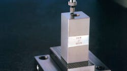
All measurements were performed on a Pratt & Whitney Labmaster Standard Measuring System (Figure l.).
METHOD 1: BETWEEN FLATS
Measuring a ball between flats seems to be the most common method. If you have measured balls using a micrometer, you quite probably used this method. It is simple and easily applied, yet it has some drawbacks.
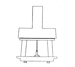
Typically the ball is positioned between a flat anvil and a flat measuring probe (Figure 2). The accuracy of the measurement is dependent on the flatness and parallelism of the anvils, coupled with the ability to repeatably locate the ball.
Typically this method relies on mastering with gage blocks which requires that the gage blocks be wrung to the anvil. This procedure may introduce wringing and temperature errors. And placing balls (especially small ones) between the anvils, without occasionally dropping one, may be difficult to do.
These drawbacks may be somewhat alleviated by using an instrument that has anvils on a vertical axis, using a master ball to set the gage, and by using a template to repeatably position the ball. This method is best suited for low volume, low accuracy applications.
METHOD 2: THREE-BALL ANVIL
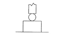
The three-ball anvil is used for comparative measurements. It is a fast and relatively accurate method of measuring many balls of similar size. A three-ball anvil is just what the name implies: a nest of three balls, where each ball contacts the two other balls and a common plane (Figure 3). To ensure accuracy, the plane that supports the three balls should be square to the measurement axis.
The three-ball anvil is easily mastered with a master ball. The ball to be measured is then placed in the three-ball nest and is engaged by a flat anvil. The three-ball anvil is accurate over a limited range. A scale factor can be entered that compensates for the slope at the points of contact between the measurement ball and the nest. If the nest and measurement balls are all of the same diameter, this scale factor is 0.8989795 and the range of balls that can be measured is Range = D ± √ 14.5 x D x E.
| Where: | D = Diameter of Ball Anvil balls |
| E = Error at end of range |
| Example: | If D=0.500000" and E=0.000001" |
| Then Range = 0.500000 ±0.0027" | |
| (0.4973 to 0.5027") |
The three-ball anvil method is well suited for production applications. It offers very repeatable positioning and the ability to spin the ball to check for diameter variation.
METHOD 3: INTERMEDIATE BLOCK
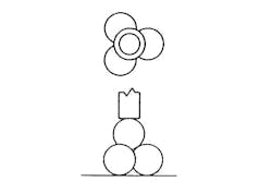
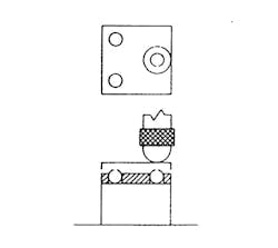
The intermediate block method is not as common as the methods discussed thus far, but offers higher accuracy. Three balls (two reference balls and one measurement ball}, positioned by a three-hole template, sit on a flat anvil. A thin and flat gage block (0.100 in. is OK) sits on these balls, and a radius-tipped probe positioned so its axis intercepts the center of the measurement ball (Figure 4) engages the thin block.
A datum is set by lowering the probe directly on the anvil (minus block, template, and balls) and entering penetration minus the thin block size as the zero position. The scale factor could be set up previously by using two gage blocks or by defining the laser wavelength of light (if laser interferometer).
Parallelism between the gage block and anvil is maintained by using reference balls from the same lot as the measurement ball. Measurement error due to out of parallelism between the gage block and anvil can be minimized by accurately positioning the centerline of the probe over the measurement ball.
While this intermediate block method is the most time-consuming, it is the most accurate of the four methods we discuss.
METHOD 4: CORNERCUBE ANVIL
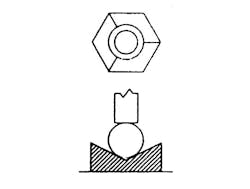
The cornercube anvil is comprised of three planes and resembles the inside comer of a box (Figure 5-above). In use, the ball to be measured self-centers and in the process, makes point contact with the three planes.
The fourth point of contact is established when a flat probe contacts the part. Since the four planes that contact the ball always maintain the same angle, changes in probe position as a result of changes in ball size is a linear function. And with the output being a linear function of the input, the cornercube anvil lends itself to mastering over a full range by using just two master balls.
For the cornercube anvil to work accurately, all four planes that contact the ball must be flat well within the expected measuring accuracy. Cosine error due to anvil out of squareness with the measuring axis is eliminated by using two-point mastering.
With the cornercube anvil offering repeatable positioning, the ability to spin the ball to check for runout, simple two-point mastering, linearity over the full range, and insensitivity to misalignments, it is well suited for production applications.
The repeatability of this anvil is well suited for checking lot diameter variation. And when mastered with the appropriate master balls, it allows for measurement of size and size variation with an accuracy that is within one-quarter of the allowable ball gage variation (Ref MIL-STD-45662A).
SUMMARY
Clearly, no single instrument or method is appropriate for all applications. Indeed, the measurement method used should match the requirements of the application.
When measuring a small number of balls, where accuracy is not terribly critical, (from grade 10 to grade 1,000), the between flats method will suffice, providing the flatness and parallelism of the anvils permit the required accuracy.
The three-ball anvil method is well applied to the comparative measurement of ball lots (all grades).
When measuring master balls (0.75" and smaller), the intermediate block method is best suited to deliver high accuracy results.
The cornercube anvil can accommodate the broadest range of applications. Measurement of all grades of small or large-quantity ball lots, 0.003 to 3.0-in. in diameter can be reliably and quickly performed with this method. When both accuracy and speed are important, we have found the cornercube anvil offers an optimum balance.
