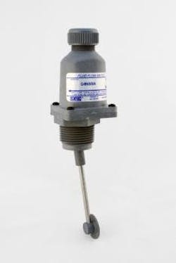
Q-8N Fluid Flow Switch
8 to 1900+ GPM, for pipes 1? – 10?+
Component Recognized (E85349)
Noryl Engineering Plastic (PPO) Polyphenylene Oxide During normal operations flow switches increase efficiency, save time and money by the continuous monitoring of deviations from optimum flow rates. During emergency conditions flow switches signal system malfunctions such as line breakage, pump failure, incorrect valve opening or closing, pipe, valve or filter clogging, etc.
Typical Working Fluids
- For use in corrosive liquids such as mild acid and base solutions and related fluids.
- Extensive chemical list is available (see here).
For use in highly particle-contaminated liquids such as:
- Contaminated Groundwater
- Machine Cutting Oils
- Medium Slurries
- Rusty Coolant Water
- Sea Water
- Sewage
- Waste Water
Special Features
- Particle contamination resistance is provided by a single convolute elastomeric seal which is continually flushed by working fluid flow.
- Wetted surfaces of Noryl, 316 Stainless Steel, EPDM Elastomeric Standard (Viton Special Order.)
- Continuous adjustment while operating
- Responds to flow only, independent of line pressure, temperature, environment
- Temperature to 180°F continuous.
- Line pressure to 50 psig operating – 100 psig nonoperating
- SPDT 15 amp switching capacity model or Dry Computer/PLC Interface model
- Maintenance and checkout is a snap for your present personnel using an uncomplicated standard test meter.
- Maximum flow range flexibility is provided by three adjustment options:
- Option 1 – Continuous adjustment while operating via FORCE/BALANCE spring
- Option 2 – Step incremental adjustment via drag disk size change
- Option 3 – Continuous
Available with Optional Filter Boot For Use In Highly Particle Contaminated Liquids
Model Selection Chart
| Pipe Size | Flow Limits Between Which Switch Point May Be Set (GPM) | Model Part # (Power Cable Interface Option 1 or 2) |
|---|---|---|
| 1 | 8–13 | Q-8N / 1 / 2 / — |
| 18–28 | Q-8N / 1 / 1 / — | |
| 1.5 | 15–30 | Q-8N / 2 / 3 / — |
| 25–50 | Q-8N / 2 / 1 / — | |
| 2 | 25–50 | Q-8N / 2 / 3 / — |
| 50–105 | Q-8N / 2 / 1 / — | |
| 2.5 | 35–80 | Q-8N / 2 / 3 / — |
| 80–155 | Q-8N / 2 / 1 / — | |
| 3 | 50–90 | Q-8N / 3 / 3 / — |
| 90–180 | Q-8N / 3 / 1 / — | |
| 4 | 75–155 | Q-8N / 3 / 3 / — |
| 155–310 | Q-8N / 3 / 1 / — | |
| 5 | 120–245 | Q-8N / 3 / 3 / — |
| 245–480 | Q-8N / 3 / 1 / — | |
| 6 | 180–350 | Q-8N / 3 / 3 / — |
| 350–700 | Q-8N / 3 / 1 / — | |
| 8 | 300–600 | Q-8N / 3 / 3 / — |
| 600–1,200 | Q-8N / 3 / 1 / — | |
| 10 | 500–950 | Q-8N / 3 / 3 / — |
| 950–1,900 | Q-8N / 3 / 1 / — |
Hysteresis (% Flow Change to Activate/Deactivate Switch)
- ? 10% at upper end of flow range
- ? 30% at lower end of flow range
Differential pressure drops across unit (Normal Operating Conditions)
- 1? – 3? pipe – less than 0.5 psi
- 4 – 10? pipe – negligible
Working Line Pressure
- 50 psig max. @ 180°F Max operating
- 100 psig @ 180°F Max non-operating
Wetted Surfaces
- Noryl – (10% glass fibers)
- 316 Stainless Steel Standard
- EPDM Elastomer (Viton Special Order)
Electrical Switch Characteristics
- SPDT
- 15 amp, 1/2 hp @ 125 or 250 VAC
- 1/2 amp @ 125 VDC (Tungsten lamp load)
- UL and CSA Listed
- 10,000,000 Operations Median
Model Q-8N can also be fitted with a SPDT Gold Cross Bar Switch for computer/PLC interface. Maximum Continuous Temperature: 180°F (may be extended to 200° for short periods). Optional Filter Boot Available in EPDM, (Viton Special Order) Weight: 1/2 lb.
Installation Dimensions


