
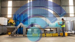


The ability to mount and move equipment is essential to any modern manufacturing plant. Many factory and machine setups have doors, cages, containers, and panels that move to allow workers access to the product or machine, as well as provide safety for the operator when closed. One of the most common methods of moving objects on the factory floor involves the use of linear motion bearings.

Linear motion bearings, or linear slides, comprise a linear system with raceways that use bearing sliders. The bearings can be of the ball, linear roller, magnetic, or even fluid variety. The Compact Rail from Rollon Corp. is an example of linear motion bearing. It has steel linear rails with induction-hardened raceways and use hardened steel precision radial ball bearing sliders. Rollon Corp. has three recent case studies using the Compact Rail that provide design insight into how to design factory equipment with linear motion bearings.
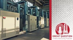
Control Micro Systems Laser
The Control Micro Systems Laser (CMS Laser) provides drilling, cutting, and welding capabilities for laser-based applications. One of the jobs from CMS Laser was manufacturing stovetop laser-etching machines for an appliance company. The laser-etching machine incorporated heavy sliding doors which were required to open wide enough to load the stainless-steel stovetops for etching. The initial linear motion bearings installed were subjected to airborne dust and debris byproducts from the laser-etching process. The bearings were becoming jammed with contaminants.

The design recommendation for CMS Laser was to upgrade to linear motion bearings where the bearings use large rolling elements that can pass over the debris. The initial bearings used were tiny recirculating ball bearings. There was little clearance in the raceways so even small pieces of debris were interfering with the balls. By increasing the diameter of the bearings, they would be able to roll over different kinds of debris and contaminants like metal chips, plastic particulates, or dust without impeding movement.
Another solution is to use bearing sliders that are enclosed to prevent debris from entering the linear guide rail. Ultimately, CMS Laser chose the TLC and ULC Compact Rail for its load-carrying capacity. The machine doors on the laser-etching device weighted more than 200 lb. The linear rail needed to support the cantilever load. The Compact Rails chosen were able to handle 15,000 and 100,000 Nm force in both the radial and axial directions, respectively.
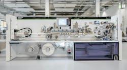
Youngblood Automation

Similar to CMS Laser, Youngblood Automation designs aluminum extrusion machine guarding and sliding guard fences. The cantilever setup of the fences requires linear bearings that can handle high-moment loads. When constructing the sliding guards, engineers fix the rollers onto the structural frame and then mount the rails on the backside of the moving gate or guard panel.
The guard panel is cantilevered out over the opening, allowing the guard to roll back while keeping the opening clear of any obstructions. The cantilever moment created by the guards can generate moment loads up to 136 N-m spread over four rollers within the bearing, often with four rollers per bearing assembly.
The major design concerns for Youngblood Automation was to find a robust enough bearing that could handle high loads, maintain rigidity, move smoothly, and fit into a tight space as it's important to keep the guard panel as close as possible to the fence to prevent harm to an operator by someone reaching through the opening.
The solution was to use a linear guide rail with an adjustable preload slider and one that could compensate for deviations in the mounting structure.
This allows for the engineers at Youngblood Automation to set the preload on the rail and set the desired clearance. Knowing one’s preload along with their ultimate moment load for cantilever operation is key to selecting the appropriate linear rail. Youngblood Automation used the Compact Rail for large-scale applications and Rollon’s X-Rail—capable of loads up to 1,600 N—for small-scale applications.
Systems Integrator N-III
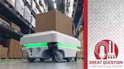
When it comes to automation technology, robot-automated guide vehicles, and pick-and-place systems are just as important as the smaller, simpler structures that are required to interface with the high-tech systems. Systems integrator N-III, Inc. devised a simple large-scale solution to improve the efficiency of an existing warehouse automated packaging-staging module.
Each module consists of four chutes that feed packages from the top of the system down to the station operator. The operator is notified of the order and, from there, can pull it out, package it, and place it onto a conveyor belt beneath the chutes. N-III wanted to incorporate support platforms onto the design of this existing structure that operators could use to box the finished orders.

N-III simple design solution was creating tables made of strong ply, which they capped with ABS plastic. These ABS “tops” were water jet cut and served as the template to rout the tables from the ply. The tables were then mounted onto a linear slider, which was mounted simply into a standard aluminum extrusion.
The workers could then slide a table along the length of the chutes when needed. There is one table per four modules and the tables can travel across the different modules (up to 12), maximizing design flexibility and minimizing the number of tables that need to be installed.
The design considerations taken by N-III related to finding an appropriate structure that could handle the moment load created by the weight of the package. N-III engineers ran a finite element analysis test to analyze and compare system stress under loads using a 1 × 1 and 1 × 2 lateral bar; they found that the 1 × 2 bar could handle the high loads of the heavy packages.
Also, the engineers had to figure out a way to attach the tables to the structure without any additional drilling or the use of T-nuts. T-nuts would have been a difficult installation task and more expensive than the aluminum sliders.
The engineers designed pre-drilled and tapped bars that, once inserted into the extrusions, aligned with the track’s 4,000 existing bolt holes.
Lastly, the use of linear motion bearings provides the machine builders with a self-aligning system. The Compact Rail by design is tolerant of misalignment and can absorb alignment errors in one or two axes due to its rail geometry. They can rotate up to 2 degrees relative to the rail without affecting functionality or increasing wear. This provided design freedom and cost reduction for the system.